If your main purpose is to control your RC5-1 rotator from a computer, and accept that the read out on the controller box itself is not 100%, is this the easy way to do so.
I run a RC5-1 rotator from a computer using the K3NG software.
As the rotator is not from start equipped with interface to a computer, I searched the internet for help, and the only on that came up was a solution I found at the www.pianetaradio.it homepage.
I tried it, but found the readout unstable when using the pstrotator program.
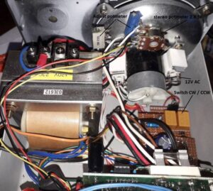
Looking inside the control box I found that the potmeter (see picture) used to control the rotator could be replaced with a stereo potmeter, so the readout was totally separated from the control box itself.
The readout principle in the K3NG software is like a voltmeter, so I made a test with one of the small Arduino programs made for measuring DC volt.
What I was measuring was the voltage between GND and the 5V pin through the middle arm on the potmeter. It showed that the voltage went for 0 to 4.8V when I activated the rotator switch on the control box.
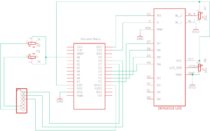
With the K3NG software, I got readout in degrees as wished. I have put in two variable resistors, 1K each is to fine adjust the readout.
My rotator is equipped with a 5k lin potmeter, so check that because the sketch says 1K.
I have tried several stereopotmeter, but it is rather difficult to find any that match 100%. Even you find at potmeter with 300 degrees mechanical turn, the electrical turn often is 270 degrees.
I have put in 2 trimmers 200 ohm each in the control box to compensate a bit, but cannot get 100% match on the control box itself, but 100% on the screen.
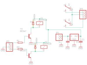
The switching circuit to control CW and CCW is inspired from K3NG, driving 2 12V relays, supplied with 2 optocouplers to separate the Arduino from the control box.
The voltage for the relays, has been taken from one of the light bulbs, where I found about 12 AC. Via a simple DC psu, it gave me the 12 DC.
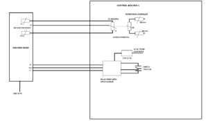
As you can see, there are no electrical connection between the Arduino and the control box.
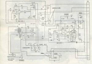
Below is the circuit of the different parts of the setup. The sketch can be downloaded here: rc5-1
